http://www.ermicro.com/blog/?p=771
The servo motor is widely used in model hobbyist such as airplane R/C model for moving the rudder, ailerons, elevators and acceleration control or in the car R/C model for steering and acceleration control. In this tutorial we will learn how to control the servo motor as well as the simple close loop control algorithm for this servo motor.
The servo motor basically is a high quality geared DC motor equipped with electronic circuit for controlling the DC motor rotation direction and position. Currently there are two types of servo motor available on the market, the first one is called standard servo and the other one is calledcontinues servo; standard servo can rotate to maximum (clockwise or counterclockwise) of 120 to 180 degrees while continues servo can rotate up to 360 degrees in both direction.
The Servo Motor
The servo motor use PWM signal for controlling the DC motor; unlike normal PWM usually used in ordinary DC motor; this PWM signal is not use for controlling the rotation speed, instead it is use for controlling the motor direction or position. Most servo motor will work well on 50 Hz of PWM frequency; this mean the PWM signal should have a period of 20ms. The electronic circuit inside the servo motor will response to the PWM signal width; the 0.7ms to 1ms PWM width will make the servo motor to turn clockwise (CW), the 1.7ms to 2ms PWM width will make the servo motor to turn counterclockwise (CCW). For the standard servo the 1.5ms PWM width will turn the servo motor to its center.

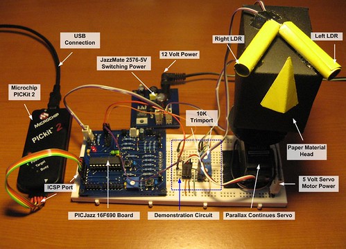
The exact PWM width is depend on the servo motor types and brands; on this tutorial we will use the Parallax Continues Servo which using 1ms and 2ms respectively. The Parallax servo motor consists of three wires colored with White, Red and Black. The Red and Black wires go to the Vcc and Gnd, while the White wire is use to feed the PWM signal from the PIC 16F690 microcontroller I/O port.
Driving the servo motor using PIC 16F690 microcontroller might be simple as you thing at the first time; we just use the PIC PWM peripheral to do the job (you could learn of how to use the PIC PWM peripheral on the article
H-Bridge Microchip PIC Microcontroller PWM Motor Controllerposted on this blog), but looking at the PIC 16F690 datasheet with the 8 Mhz of internal frequency clock (use in this tutorial) and using maximum prescaler of 16 (TIMER2) the minimum PWM frequency we could achieve can be calculated using this formula:
PWM period = [( PR2 + 1) ] x 4 x Tosc x (TMR2 prescaler value) second
Using maximum PR2 register value of 0xFF (255 decimal), we will get this result:
PWM period = (255 + 1) x 4 x (1 / 8000000) x 16= 0.002048 second
PWM frequency = 1 / PWM period = 1 / 0.002048 = 488.28 Hz
The 488.28 Hz frequency is still too high from the servo motor working frequency of 50Hz; therefore this leads us to these three methods bellow:
- Keep using the PIC PWM peripheral and lower the operation frequency by setting theOSCCON register and PR2 register until it meets the servo motor frequency requirement. This approach will secrify the program execution speed as we will operate the PIC Microcontroller with the 500 khz clock speed, so we simply not choose it.
- Secondly, we create our own PWM function to mimic the PWM signal as follow: turn on the PORT, make some 2 ms delay, turn off the PORT, and make some 18 ms delay and so forth. This approach is what I called a dirty method which is not the efficient way to do it, so we just drop this method.
- The third approach is to use the PIC 16F690 microcontroller TIMER0 with the interrupt to actually generate the PWM signal as the TIMER0 have wider prescaler to choose comparing to the TIMER2, but unfortunately the PWM peripheral on the PIC 16F690 only work with TIMER2 not TIMER0. Therefore we will make this TIMER0 as our PWM base generator for driving the servo motor on this tutorial. The principal we learn here could be applied to the other type of PIC Microcontroller or AVR Microcontroller as well.
Instead of just demonstrating the servo motor to rotate clockwise and counterclockwise, I decide to make it more challenging and attractive by putting the LDR (light dependent resistor) as the light sensor to our servo motor and make this servo motor to behave as the light seeking machine; …hey this sound like we are touching the robotics field; …hmm yes isn’t it cool, as we know most of the embedded robotics hobbyist widely use the servo motor for robot’s arms, walkers robots, light seeking robot (know also as photovore robot) and many more.
The LDR (Light Dependent Resistor)
By just looking at the name, is clear that this is the type of resistor that its resistance depends on the light intensity; it’s also called photoresistor, made from the Cadmium Sulfide (CdS) one of the semiconductor material. The LDR will response to light it received, the brightest the light the smaller its resistance and vise versa; on the complete darkness the LDR resistance will become very high (about 150K Ohm; for the LDRs I use in this tutorial)
From the above circuit diagram we connect serially the LDR with the 10K trimport and use it as the voltage divider circuit to the PIC 16F690 analog input
AN4 and
AN5 (you could learn about
Basic Resistor Circuit posted in this blog); therefore the variation on the light intensity received by the LDR will result on the variation of the voltage level to the PIC analog input port. Because of the LDR resistance vary widely among the types and brands, therefore we use the trimport and I suggest that you preset it to about 5 K Ohm on the first time and later on you can adjust it as needed.
The LDR pairs will be functioned as the light sensor that controlled the servo motor position toward the light source; therefore to get the maximum performance we put these two LDRs inside the paper tube in such a way that their position is about 45 degrees away from the light source center (see the top view picture above).
The Light Seeking Head Construction
One of my favorite construction material is to use a thick paper (…yes it’s a paper) for fast prototyping as its easy to cut, bend, light weight and quiet strong; our seeking light head project use just a thick paper to demonstrate the servo motor concept or what we usually called it as the proof of concept (POC); so let’s do the cut and paste; and of course you could experiment with any kind of head forms or faces as you like and these following pictures can be use as the starter.
The following is the list of hardware and software used in this tutorial:
1. Thick paper, scissor, glue, duct tape and spray paint for our light seeking head
2. One continues servo motor (in this project I’am using Parallax continues servo)
3. Two LDR
4. Two Trimport 10K
5. PICJazz 16F690 learning board from ermicro (the
schema)
6. JazzMate 2576-5V power board, the 5 volt switching power supply
7. Microchip PICKit2 Programmer
8. Microchip MPLAB IDE v8.0 or higher
9. HITEC PICC-Lite PICC-Lite Version 9.60PL1
Now let’s take a look at the C code that makes this thing happen:
// ***************************************************************************
//  File Name    : servo.c
//  Version      : 1.0
//  Description  : Servo Motor Controller
//                 Using TIMER0 for Generating Servo PWM
//  Author       : RWB
//  Target       : PICJazz 16F690 Board
//  Compiler     : HITECT PICC-Lite Version 9.60PL1
//  IDE          : Microchip MPLAB IDE v8.00
//  Programmer   : PICKit2
//  Last Updated : 03 Jan 2009
// ***************************************************************************
#include <pic.h>
/*   PIC Configuration Bit:
**   INTIO     - Using Internal RC No Clock
**   WDTDIS    - Wacthdog Timer Disable
**   PWRTEN    - Power Up Timer Enable
**   MCLREN    - Master Clear Enable
**   UNPROTECT - Code Un-Protect
**   UNPROTECT - Data EEPROM Read Un-Protect
**   BORDIS    - Borwn Out Detect Disable
**   IESODIS   - Internal External Switch Over Mode Disable
**   FCMDIS    - Monitor Clock Fail Safe Disable
*/
__CONFIG(INTIO & WDTDIS & PWRTEN & MCLREN & UNPROTECT \
  & UNPROTECT & BORDIS & IESODIS & FCMDIS);
// Using Internal Clock of 8 Mhz
#define FOSC 8000000L
// Servo definition and variables
#define MAX_VALUE 200
#define CCW_ROTATION MAX_VALUE - 20
#define CW_ROTATION MAX_VALUE - 10
#define STOP_ROTATION MAX_VALUE
#define THRESHOLD_VALUE 50
unsigned char pulse_max=0;
unsigned char pulse_top=0;
unsigned char top_value = 0;
static void interrupt isr(void)
{
  if(T0IF) {             // TIMER0 Interrupt Flag
    pulse_max++;            // Pulse Max Increment
    pulse_top++;            // Pulse Top Increment

    /* MAX_VALUE=200 turn off the pulse */
    if (pulse_max >= MAX_VALUE) {
      pulse_max=0;
      pulse_top=0;
      RC2=0;                // Turn off RC2
    }

    /* top_value = MAX_VALUE - n, n=10: 10 x 0.1ms = 1.0ms, n=20: 20 x 0.1ms = 2.0ms */
    /* 2ms -> CCW Rotation, 1ms -> CW Rotation */
    if (pulse_top == top_value) {
      RC2=1;                // Turn On RC2
    }
    TMR0 = 156;             // Initial Value for 0.1ms Interrupt
    T0IF = 0;      // Clear TIMER0 interrupt flag
  }
}
void main(void)
{
  unsigned char ldr_left;
  unsigned char ldr_right;
  int ldr_diff;
OSCCON=0x70; // Select 8 Mhz internal clock
  /* Initial Port Used */
  TRISC = 0x03;        // Set RC0 and RC1 as input others as Output
  ANSEL = 0x30;        // Set PORT AN4 and AN5 as analog input
  ANSELH = 0x00;       // Set PORT AN8 to AN11 as Digital I/O
  PORTC = 0x00;        // Turn Off all PORTC
  /* Init Servo Pulse */
  pulse_max=0;
  pulse_top=0;
  top_value = MAX_VALUE; // top_value = MAX_VALUE: Servo Motor Stop
  /* Initial ADC */
  ADCON1=0b00110000;   // Select the FRC for 8 Mhz
  /* Init TIMER0: Period: Fosc/4 x Prescaler x TMR0
     0.0005 ms x 2 * 100 = 0.1 ms */
  OPTION = 0b00000000; // 1:2 Prescaller
  TMR0=156;            // Interupt every 0.1 ms
  T0IE = 1;         // Enable interrupt on TMR0 overflow
  GIE = 1;         // Global interrupt enable

  for(;;) {
    /* Read the ADC here */
    ADCON0=0b00010001;       // select left justify result. ADC port channel AN4
    GODONE=1;              // initiate conversion on the channel 4
    while(GODONE) continue;  // Wait for ldr_left conversion done
    ldr_left=ADRESH;         // Read 8 bits MSB, Ignore 2 bits LSB in ADRESL
    ADCON0=0b00010101;       // select left justify result. ADC port channel AN5
    GODONE=1;              // initiate conversion on the channel 5
    while(GODONE) continue;  // Wait for ldr_right conversion done
    ldr_right=ADRESH;        // Read 8 bits MSB, Ignore 2 bits LSB in ADRESL

    /* Get the different */
    ldr_diff=ldr_left - ldr_right;

    if ((ldr_diff >= -THRESHOLD_VALUE) && (ldr_diff <= THRESHOLD_VALUE)) {
      top_value = MAX_VALUE;     // Stop the Servo Motor
    } else {
      if (ldr_diff > THRESHOLD_VALUE) {
        top_value = CCW_ROTATION;  // Counterclockwise Rotation
      } else {
        top_value = CW_ROTATION;   // Clockwise Rotation
      }
    }
  }
}
/* EOF: servo.c */
PIC Microcontroller TIMER0 Peripheral
The heart of the servo motor PWM pulse is rely on the PIC TIMER0 peripheral; this TIMER0 together with the interrupt service will be used as our servo motor base PWM pulse generator. The TIMER0 peripheral is actually the 8-bit counter that always increase it count base on the clock pulse supply to it. The PIC microcontroller TIMER0 counter use the TMR0 register to hold the counted number, each of the clock pulse will increase the TMR0 register value by 1 until it reach its maximum value of 255 and start all over again from 0 (overflow); and when this happening the PIC TIMER0 peripheral will rise the interrupt signal. The interrupt signal raised by the PIC TIMER0 peripheral will be interpreted by the microcontroller as this following explanation:
1. Stop whatever you are doing right now
2. Save the current execution address for later used in memory; this area of memory is known as the stack area
3. Jump to the assigned TIMER0 interrupt service address
4. Start execute the code in the TIMER0 interrupt service address
5. Return back to your last task by loading the last execution address in the stack area and continue execute the code from it.
The principal we use here is to set the TMR0 register to overflow every 0.1 ms and set our own counter variable (pulse_max) to count up to maximum 200; this will give us the constant 20 ms period which is the same as 50 Hz frequency required by our servo motor.
The TIMER0 period could be calculated using this formula bellow:
TIMER0 period = [(TMR0 + 1)] x 4 x Tosc x (TIMER0 prescaler value) second
By selecting the TIMER0 prescaler of 2; PS2=0, PS1=0 and PS0=0 bits in OPTION_REGregister and initial the TMR0 register value to 156 (99 more counts to reach its maximum value of 255) with the system frequency clock of 8 Mhz, the PIC microcontroller TIMER0 overflow period can be calculated as follow:
TIMER0 period = [((255 - 156) + 1)] x 4 x 1/8000000 x 2 = 0.0001 second = 0.1 ms
The following C code is used to initialize the PIC 16F690 TIMER0 peripheral:
/* Init TIMER0: Period: Fosc/4 x Prescaler x TMR0
   0.0005 ms x 2 * 100 = 0.1 ms */
OPTION = 0b00000000; // 1:2 Prescaller
TMR0 = 156;          // Interupt every 0.1 ms
T0IE = 1;      // Enable interrupt on TMR0 overflow
GIE = 1;      // Global interrupt enable
In order to generated the PWM pulse, we need to have two separate variable counter here; one is the pulse_max variable used for resetting the RC2 port (logical “0“) which connected to the servo motor and secondly is the pulse_top variable used to set the RC2 port; thepulse_top variable will be compared to the top_value variable; and if it equal than we will set the RC2 port (logical “1“).

From the timing diagram above the pulse_max variable is used to hold our own PWM counter and the pulse_max value increase every 0.1ms (TMR0 overflow). By the time it reaches the maximum value of 200 than we will reset the RC2 port together with the pulse_max variable and the pulse_top variable. The pulse_top value also increase every 0.1 ms and its value constantly compared to the top_value variable value; when it equal we will set the RC2 port (logical “1“); for example by setting the top_value variable to 190, means when the pulse_topvariable reach 190, the RC2 port will be set and when pulse_max reach 200 the RC2 port will be reset, this will make our servo motor to turn clockwise. Again by setting the top_valuevariable to 180 the servo motor will turn counterclockwise as it receive the 2 ms of PWM signal. Bellow is the code inside the TIMER0 interrupt service routine:
if(T0IF) {    // TIMER0 Interrupt Flag
  pulse_max++;            // Pulse Max Increment
  pulse_top++;            // Pulse Top Increment
/* MAX_VALUE=200 turn off the pulse */
  if (pulse_max >= MAX_VALUE) {
    pulse_max=0;
    pulse_top=0;
    RC2=0;                // Turn off RC2
  }
  /* top_value = MAX_VALUE - n, n=10: 10 x 0.1ms = 1.0ms, n=20: 20 x 0.1ms = 2.0ms   */
  /* 2ms -> CCW Rotation, 1ms -> CW Rotation */
  if (pulse_top == top_value) {
    RC2=1;               // Turn On RC2
  }
  TMR0 = 156;             // Initial Value for 0.1ms Interrupt
  T0IF = 0;               // Clear TIMER0 interrupt flag
}
Because the TIMER0 interrupt flag bit (T0IF) in the INTCON register is not automatically reset to0, therefore we have to manually reset it inside the TIMER0 interrupt function.
As you see by using this method the program code for controlling the servo motor will be much easier now as we only assign the correct value to the top_value variable and let the PIC microcontroller TIMER0 peripheral do the job by supplying the required PWM signal to the servo motor as it shown on this following C code example:
#define MAX_VALUE 200
#define CCW_ROTATION MAX_VALUE - 20
#define CW_ROTATION MAX_VALUE - 10
#define STOP_ROTATION MAX_VALUE
top_value = MAX_VALUE;     // Stop the Servo Motor
top_value = CCW_ROTATION;  // Counterclockwise Rotation
top_value = CW_ROTATION;   // Clockwise Rotation
The Light Seeking Sensor
As I mention before that instead of just making our servo motor to rotate clockwise (CW) or counterclockwise (CCW); we will use it to position our paper head toward the light source. This can be achieve by using the pair of LDRs to detect the light source and base on the light intensity information received by the LDR pair; we make the servo motor to rotate in such away that our head paper will always facing the light source as seen on this following picture
The LDR pairs will constantly give the light source position feedback to the servo motor so it can always turn our paper head toward the light source; this is known as the close loop controlwhich is one of the most important topics in the embedded system.
The method of controlling the paper head we use here is called the “on-off controller” or “bang-bang controller“; this is the simplest method of controlling usually found in the heater, air-condition and refrigerator for controlling the temperature or in the line follower robot and summo wrestling robot. The more advanced controlling method is called the “PID (Proportional, Integral, Derivative) controller” which is used such as in motor speed controlling, however we will not discuss this controlling method on this tutorial, but once you understand and implement the principal of the basic close loop control presented here, later on it will be easier for you to learn this PID controlling method.
The algorithm we use here is base on the differential value returned by the left LDR and the right LDR; the positive result will rotate the servo motor counterclockwise and the negative result will rotate the servo motor clockwise. The servo motor will keep rotating until the different result is zero; which mean the paper head is facing the light source.
To make the servo motor rotate smoothly we use the threshold value or known as thehysteresis band in the on-off controller method, this mean if the different result is within the hysteresis band the servo motor will always stop and if the different result is outside the hysteresis band the servo motor will start to rotate counterclockwise or clockwise as shown in this following time diagram:
The following is the C code for implementing the on-off controller method with the hysteresis band:
#define THRESHOLD_VALUE 50
/* Get the different */
ldr_diff=ldr_left - ldr_right;

if ((ldr_diff >= -THRESHOLD_VALUE) && (ldr_diff <= THRESHOLD_VALUE)) {
  top_value = MAX_VALUE;     // Stop the Servo Motor
} else {
  if (ldr_diff > THRESHOLD_VALUE) {
    topvalue=CCW_ROTATION;  // Counterclockwise Rotation
  } else {
    topvalue=CW_ROTATION;   // Clockwise Rotation
  }
}
The LDRs value is read by the PIC ADC peripheral through the analog input port channel 4 (AN4) and channel 5 (AN5); when the left LDR received more light compare to the right LDR the voltage level input on the AN4 port will be more higher and the different result in ldr_diff variable will be positive; when the right LDR received more light than the voltage level input on the AN5 port will be more higher and the different result in ldr_diff variable will be negative. The following is the C code used to read the LDR’s voltage level:
/* Read the ADC here */
ADCON0=0b00010001;       // select left justify result. ADC port channel AN4
GODONE=1;              // initiate conversion on the channel 4
while(GODONE) continue;  // Wait for ldr_left conversion done
ldr_left=ADRESH;         // Read 8 bits MSB, Ignore 2 bits LSB in ADRESL
ADCON0=0b00010101;       // select left justify result. ADC port channel AN5
GODONE=1;              // initiate conversion on the channel 5
while(GODONE) continue;  // Wait for ldr_right conversion done
ldr_right=ADRESH;        // Read 8 bits MSB, Ignore 2 bits LSB in ADRESL
Inside the C Code
This program is start by initializing the PIC port used in this tutorial and continue with the PIC ADC peripheral clock selection in the ADCON1 register for using the 8 Mhz internal clock and the last is to initial the PIC TIMER0 peripheral. After the initialization process the program enter the endless loop where we read the voltage level returned by the left LDR and the right LDR and do the “bang-bang controller” algorithm.
/* Initial Port Used */
TRISC = 0x03;        // Set RC0 and RC1 as input others as Output
ANSEL = 0x30;        // Set PORT AN4 and AN5 as analog input
ANSELH = 0x00;       // Set PORT AN8 to AN11 as Digital I/O
PORTC = 0x00;        // Turn Off all PORTC
It’s important to remember that we have set the port to the analog input mode first before we use it for reading the analog signal.
Downloading the Code
After compiling and simulating your code hook up your PICKit2 programmer to the PICJazz 16F690 board ICSP port turn the PICJazz 16F690 power. From the MPLAB IDE menu selectProgrammer -> Select Programmer -> Pickit2 it will automatically configure the connection and display it on the PICkit2 tab Output windows:
Now you are ready to down load the code from MPLAB IDE menu select Programmer ->Program; this will down load the HEX code into the PICJazz 16F690 board:
Now just relax and enjoy your light seeking head in action:
Bookmarks and Share