Stepper Motor Interfacing with NodeMCU
Introduction
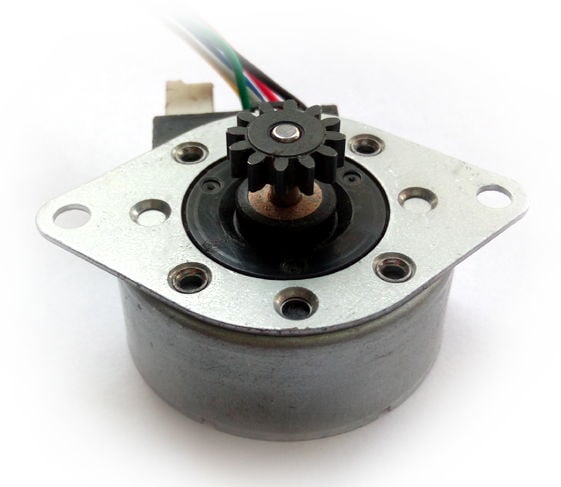
Stepper Motor
Stepper motor is a brushless DC motor that divides the full rotation angle of 360° into number of equal steps.
The motor is rotated by applying certain sequence of control signals. The speed of rotation can be changed by changing the rate at which the control signals are applied.
For more information about Stepper Motor, its control sequence and how to use it, refer the topic Stepper Motor in the sensors and modules section.
NodeMCU GPIOs can be used to control stepper motor rotation. We can generate sequence of control signals on the GPIO pins of NodeMCU. To know more about NodeMCU GPIO refer NodeMCU GPIO with ESPlorer IDE and NodeMCU GPIO with Arduino IDE.
Interfacing Diagram
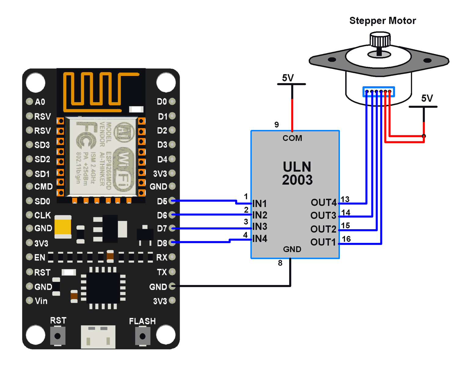
NodeMCU interface with Stepper Motor
Example
Let’s rotate a stepper motor in clockwise and counter clockwise directions alternately.
Here, we are using six wire unipolar stepper motor. Only four wires are required to control this stepper motor. The two centre tap wires of the stepper motor are connected to 5V supply.
ULN2003 driver is used to drive unipolar stepper motor.
Note: To find winding coils and their centre tap leads, measure resistance in between the leads. From centre leads we will get half the resistance value as compared to resistance between winding ends.
We can write codes for NodeMCU DevKit in either Lua Script or C/C++ language. We are using ESPlorer IDE for writing code in Lua scripts and Arduino IDE for writing code in C/C++. To know more refer Getting started with NodeMCU using ESPlorer IDE (which uses Lua scripting for NodeMCU) and Getting started with NodeMCU using Arduino IDE (which uses C/C++ language based Arduino sketches for NodeMCU).
Lua Script for Stepper Motor
wire1 = 8
wire2 = 7
wire3 = 6
wire4 = 5

_delay = 50000 --delay in between two steps. minimum delay more the rotational speed

gpio.mode(wire1, gpio.OUTPUT)--set four wires as output
gpio.mode(wire2, gpio.OUTPUT)
gpio.mode(wire3, gpio.OUTPUT)
gpio.mode(wire4, gpio.OUTPUT)

function sequence(a, b, c, d)--four step sequence to stepper motor
    gpio.write(wire1, a)
    gpio.write(wire2, b)
    gpio.write(wire3, c)
    gpio.write(wire4, d)
    tmr.delay(_delay)
end

while true do
    for i = 1 ,12 do --Rotation in one direction
        sequence(gpio.HIGH, gpio.LOW, gpio.LOW, gpio.LOW)
        sequence(gpio.HIGH, gpio.HIGH, gpio.LOW, gpio.LOW)
        sequence(gpio.LOW, gpio.HIGH, gpio.LOW, gpio.LOW)
        sequence(gpio.LOW, gpio.HIGH, gpio.HIGH, gpio.LOW)
        sequence(gpio.LOW, gpio.LOW, gpio.HIGH, gpio.LOW)
        sequence(gpio.LOW, gpio.LOW, gpio.HIGH, gpio.HIGH)
        sequence(gpio.LOW, gpio.LOW, gpio.LOW, gpio.HIGH)
        sequence(gpio.HIGH, gpio.LOW, gpio.LOW, gpio.HIGH)
    end
    sequence(gpio.HIGH, gpio.LOW, gpio.LOW, gpio.LOW)
    for i = 1 ,12 do --Rotation in opposite direction
        sequence(gpio.LOW, gpio.LOW, gpio.LOW, gpio.HIGH)
        sequence(gpio.LOW, gpio.LOW, gpio.HIGH, gpio.HIGH)
        sequence(gpio.LOW, gpio.LOW, gpio.HIGH, gpio.LOW)
        sequence(gpio.LOW, gpio.HIGH, gpio.HIGH, gpio.LOW)
        sequence(gpio.LOW, gpio.HIGH, gpio.LOW, gpio.LOW)
        sequence(gpio.HIGH, gpio.HIGH, gpio.LOW, gpio.LOW)
        sequence(gpio.HIGH, gpio.LOW, gpio.LOW, gpio.LOW)
        sequence(gpio.HIGH, gpio.LOW, gpio.LOW, gpio.HIGH)
    end
    sequence(gpio.LOW, gpio.LOW, gpio.LOW, gpio.HIGH)
end
Arduino Sketch for Stepper Motor
uint8_t wire1 = D8;
uint8_t wire2 = D7;
uint8_t wire3 = D6;
uint8_t wire4 = D5;

const uint16_t _delay = 50; /* delay in between two steps. minimum delay more the rotational speed */

void sequence(bool a, bool b, bool c, bool d){  /* four step sequence to stepper motor */
  digitalWrite(wire1, a);
  digitalWrite(wire2, b);
  digitalWrite(wire3, c);
  digitalWrite(wire4, d);
  delay(_delay);
}

void setup() {
  pinMode(wire1, OUTPUT); /* set four wires as output */
  pinMode(wire2, OUTPUT);
  pinMode(wire3, OUTPUT);
  pinMode(wire4, OUTPUT);
}

void loop() {
  /* Rotation in one direction */
  for(int i = 0; i<12; i++)
  {
    sequence(HIGH, LOW, LOW, LOW);
    sequence(HIGH, HIGH, LOW, LOW);
    sequence(LOW, HIGH, LOW, LOW);
    sequence(LOW, HIGH, HIGH, LOW);
    sequence(LOW, LOW, HIGH, LOW);
    sequence(LOW, LOW, HIGH, HIGH);
    sequence(LOW, LOW, LOW, HIGH);
    sequence(HIGH, LOW, LOW, HIGH);
  }
  sequence(HIGH, LOW, LOW, LOW);
  /* Rotation in opposite direction */
  for(int j = 0; j<12; j++)
  {
    sequence(LOW, LOW, LOW, HIGH);
    sequence(LOW, LOW, HIGH, HIGH);
    sequence(LOW, LOW, HIGH, LOW);
    sequence(LOW, HIGH, HIGH, LOW);
    sequence(LOW, HIGH, LOW, LOW);
    sequence(HIGH, HIGH, LOW, LOW);
    sequence(HIGH, LOW, LOW, LOW);
    sequence(HIGH, LOW, LOW, HIGH);
  }
  sequence(LOW, LOW, LOW, HIGH);
}


Very informative and impressive post you have written, this is quite interesting and i have went through it completely, an upgraded information is shared, keep sharing such valuable information. Desentupidora no ipiranga
回覆刪除