Tutorial: Arduino and Thumbwheel switches
Posted on 15 August 2011.
This is chapter forty of a series originally titled “Getting Started/Moving Forward with Arduino!” by John Boxall – a series of articles on the Arduino universe. The first chapter is here, the complete series is detailed here. Any files from tutorials will be found here.
[Updated 20/01/13]
In this article we go back to the past via the use of push-wheel/thumbwheel switches with out Arduino systems. Here are some examples sourced from somewhere on eBay:
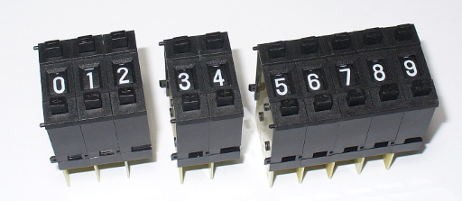
For the uninitiated, each switch is one vertical segment and they can be connected together to form various sizes. You can use the buttons to select from digits zero through to nine. There are alternatives available that have a wheel you can move with your thumb instead of the increase/decrease buttons. Before the days of fancy user interfaces these switches were quite popular methods for setting numerical data entry. However they are still available today, so let’s see how they work and how we can use them. The switch’s value is made available via binary-coded decimal. Consider the rear of the switch:
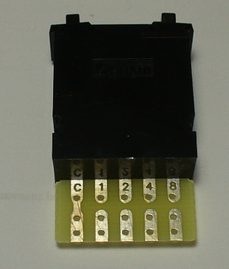
We have common on the left, then contacts for 1, 2, 4 and 8. If you apply a small voltage (say 5V) to common, the value of the switch can be measured by adding the values of the contacts that are in the HIGH state. For example, if you select 3 – contacts 1 and 2 will be at the voltage at common. The values between zero and nine can be represented as such:
By now you should realise that it would be easy to read the value of a switch – and you’re right, it is. We can connect 5V to the common, the outputs to digital input pins of our Arduino boards, then use digitalRead() to determine the value of each output. In the sketch we use some basic mathematics to convert the BCD value to a decimal number. So let’s do that now.
From a hardware perspective, we need to take into account one more thing – the push-wheel switch behaves electrically like four normally-open push buttons. This means we need to use pull-down resistors in order to have a clear difference between high and low states. So the schematic for one switch would be (click image to enlarge):
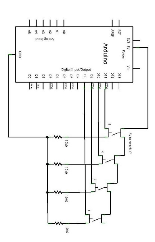
Now it is a simple matter to connect the outputs labelled 1, 2, 4, and 8 to (for example) digital pins 8, 9, 10 and 11. Connect 5V to the switch ‘C’ point, and GND to … GND. Next, we need to have a sketch that can read the inputs and convert the BCD output to decimal. Consider the following sketch:
The function readSwitch() is the key. It calculates the value of the switch by adding the numerical representation of each switch output and returns the total as its result. For this example we used a numerical display shield that is controlled by the NXP SAA1064. If you don’t have one, that’s ok – the results are also sent to the serial monitor. Now, let’s see it in action:
Ok it doesn’t look like much, but if you need numerical entry it saves a lot of physical space and offers a precise method of entry.
So there you have it. Would you actually use these in a project? For one digit – yes. For four? Probably not – perhaps it would be easier to use a 12-digit keypad. There’s an idea… But for now I hope you enjoyed reading this as much as I did writing it for you.
Update! See the addendum for using four switches at once to read four-digit numbers here.


Very informative and impressive post you have written, this is quite interesting government jobs 2021
回覆刪除sarkari naukri 2021
sarkari-job 2021
iti-govt-jobs 2021
diploma-govt-jobs 2021
10th-pass-govt-jobs 2021
12th-pass-govt-jobs 2021
railway-jobs 2021
punjab-govt-jobs 2021
delhi-govt-jobs 2021
Hey! really appreciate. I want to share some related related to Rojgar Samachar
回覆刪除NVS Recruitment
SBI Recruitment
APPSC Recruitment